Wi-Fi improves every year but even now, with the imminent launch of Wi-Fi 7, you still can’t beat old-fashioned copper wire. Ethernet cables are reliable and fast: they’re not (as) susceptible to interference and can aid wireless devices too: they’re not just for PCs, laptops and NAS boxes.
You could use Ethernet backhaul with a compatible mesh Wi-Fi system, allowing you to place your nodes further apart than Wi-Fi allows.
While you can just buy pre-made Ethernet cables and literally lay them on your floors, through doorways and up flights of stairs, it’s unsightly and a potential trip hazard. Instead, it’s best to buy proper solid-core Ethernet cable on a reel and run it to wall-mounted faceplates, such as this single-gang one from Amazon.
Note that the faceplates are rated just like Ethernet cable, so pay a little more and get at least Cat6 for future proofing.
You’ll also need a pattress box to screw the faceplate to. These are no different from those you’d buy for electrical sockets and come in a variety of depths, designed either for flush mounting (so the faceplate sits level with your wall) or surface mounting, where it isn’t possible to make a deep hole in your wall. In the photo above, you see a four-port Cat6 faceplate with a surface-mount, two-gang pattress box.
Anyway, you may know all of this already and simply want to know how to wire up one of these RJ45 wall sockets. And the reason it isn’t straightforward is because there are two wiring standards, T568A and T568B, and your Ethernet connector probably has wiring diagrams for both, as shown in the photo below, or may possibly have nothing at all: just pin numbers.
Technically, it doesn’t matter which of the two schemes you use, since T568A and T568B are both ‘straight through’ configurations. That means that the wires from pins 1 to 8 connect to the corresponding pin at the other end. But it’s best to pick T568B as it’s the most widely used, and is designed for better noise protection and signal isolation.

Importantly, and obviously, you must use the same scheme at both ends of the same cable, whichever you go for.
To connect your Ethernet cable to the faceplate you’ll need a punch-down tool like the one shown below to push the wires onto the terminals on the back of the socket. This is the proper tool for the job. It’s possible to use a small flat-blade screwdriver in a pinch, but having the proper tool always helps – and is less dangerous. Either way, there’s no need to strip the wires first: pushing them onto the terminal slices through the coating and makes a connection with the metal beneath.

You can buy these punch-down tools individually and very cheaply, but if you don’t already have an RJ-45 crimp tool for terminating regular Ethernet cables – the sort that connect a PC to the wall socket you want to wire up – you may as well buy a full kit that includes everything, including a tester so you can be sure you’ve wired it all up properly.
You can pick these up from Amazon or elsewhere for under $30. If you have a lot of sockets to wire up, you should buy a more expensive punch down tool that also cuts the excess wire for you.
Here’s which wire to connect to each pin on the back of your Ethernet wall socket. Again, we recommend using T568B. Pin numbers should be clearly marked, but if not don’t assume what’s what: they aren’t all identical.
Pin | T568A | T568B | T568A wire color | T568B wire color |
|
1 | 3 | 2 | white/green stripe | white/orange stripe | |
2 | 3 | 2 | green solid | orange solid | |
3 | 2 | 3 | white/orange stripe | white/green stripe | |
4 | 1 | 1 | blue solid | blue solid | |
5 | 1 | 1 | white/blue stripe | white/blue stripe | |
6 | 2 | 3 | orange solid | green solid | |
7 | 4 | 4 | white/brown stripe | white/brown stripe | |
8 | 4 | 4 | brown solid | brown solid |
With your Ethernet cable routed to the socket and arriving through the pattress box, strip off around 30-40mm of the external sheath, ideally using the special tool that comes in RJ45 crimping kits. You’ll see the four pairs of wires twisted together and a plastic X keeping the pairs separate. Trim off the plastic and untwist the cables.
Arrange the wires so they lay over each terminal, with the excess facing the outside of the socket, not the inside.
Use the punch-down tool to put each wire onto its terminal.

Jim Martin / Foundry
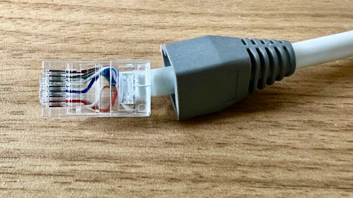
If you’re wiring an RJ45 connector to terminate an Ethernet cable to plug into a wall socket, you can also use the table above. Looking from underneath, with the release tab on the opposite side in this photo, Pin 1 is at the bottom, with Pin 8 at the top. The reason for taking the photo with the connector this way up instead of the more logical top-down view with Pin 1 at the top is that you can see the pins.
And if you are making up your own patch leads, remember to put the rubber boot on before you crimp the connector.
If you’re looking to buy pre-made ones, here are some recommendations for the best Ethernet cables from our sister site TechAdvisor.
This story originally appeared on techadvisor.com.


